Pololu 3.3V 300mA Step-Down Voltage Regulator D24V3F3
SKU : D24V3F3-300mA
Out of stock
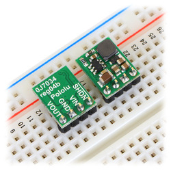
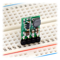
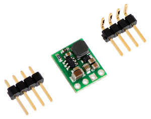
he compact (0.4″ × 0.5″) D24V3F3 switching step-down (or buck) voltage regulator takes an input voltage between 4.3 V and 42 V and efficiently reduces it to 3.3 V while allowing for a maximum output current of 300 mA. The pins have a 0.1″ spacing, making this board compatible with standard solderless breadboards and perfboards.
Overview
These buck (step-down) voltage regulators generate lower output voltages from input voltages as high as 42 V. They are switching regulators (also called switched-mode power supplies (SMPS) or DC-to-DC converters) and have a typical efficiency between 80% to 90%, which is much more efficient than linear voltage regulators, especially when the difference between the input and output voltage is large. This regulator is available with a fixed 3.3 V, 5 V, 9 V, or 12 V output, and two versions are available for each voltage, one with a 300 mA maximum output current (D24V3Fx) and one with a 600 mA maximum output current (D24V6Fx):
The regulator has short-circuit protection, and thermal shutdown prevents damage from overheating. The board does not have reverse-voltage protection.
If you need more output current, consider our D15V35F5S3 and D15V70F5S3 3.3V/5V step-down voltage regulators, which can typically deliver a continuous 3.5 A and 7 A, respectively.
Features
- Input voltage: [output voltage + dropout voltage] to 42 V (see below for more information on dropout voltage)
- Fixed 3.3 V, 5 V, 9 V, or 12 V output (depending on regulator version) with 4% accuracy
- Maximum output current: 300 mA or 600 mA (depending on regulator version)
- 550 kHz switching frequency
- 2 mA typical no-load quiescent current (20 μA typical quiescent current with SHDN = LOW)
- Integrated over-temperature and over-current shutoff
- Small size: 0.5″ × 0.4″ × 0.1″ (13 mm × 10 mm × 3 mm)
Using the Regulator
Connections
The buck regulator has four connections: shutdown (SHDN), input voltage (VIN), ground (GND), and output voltage (VOUT).
The SHDN pin can be driven low (under 0.3 V) to turn off the output and put the board into a low-power state that typically draws 20 μA. The SHDN pin can be driven high (above 2.3 V) to enable the board, or it can be connected to VIN or left disconnected if you want to leave the board permanently enabled.
The input voltage, VIN, should exceed VOUT by at least the regulator’s dropout voltage (see below for graphs of dropout voltages as a function of the load), and you must ensure that noise on your input does not exceed the 42 V maximum. Additionally, please be wary of destructive LC spikes (see below for more information).
The output voltage, VOUT, is fixed and depends on the regulator version: the D24VxF3 version outputs 3.3 V, the D24VxF5 version outputs 5 V, the D24VxF9 version outputs 9 V, and the D24VxF12 version outputs 12 V.
The four connections are labeled on the back side of the PCB, and they are arranged with a 0.1″ spacing along the edge of the board for compatibility with solderless breadboards, connectors, and other prototyping arrangements that use a 0.1″ grid. You can solder wires directly to the board or solder in either the 4×1 straight male header strip or the 4×1 right-angle male header strip that is included.
LC Voltage Spikes
When connecting voltage to electronic circuits, the initial rush of current can cause voltage spikes that are much higher than the input voltage. If these spikes exceed the regulator’s maximum voltage (42 V), the regulator can be destroyed. In our tests with typical power leads (~30″ test clips), input voltages above 20 V caused spikes over 42 V. If you are connecting more than 20 V or your power leads or supply has high inductance, we recommend soldering a 33μF or larger electrolytic capacitor close to the regulator between VIN and GND. The capacitor should be rated for at least 50 V.
More information about LC spikes can be found in our application note, Understanding Destructive LC Voltage Spikes.
Dimensions
- Size: 0.4″ × 0.5″ × 0.1″1
- Weight: 0.5 g1
General specifications
- Minimum operating voltage: 3.8 V2
- Maximum operating voltage: 42 V
- Maximum output current: 300 mA
- Output voltage: 3.3 V
- Reverse voltage protection?: N
- Maximum quiescent current: 2 mA3
Notes:
- 1. Without included optional headers.
- 2. For small loads; input voltage must be at least 4.3 V to get the full 300 output.
- 3. While enabled (SHDN = HIGH) with no load. Current draw is approximately 20 µA when SHDN = LOW.