Step-Down Voltage Regulator D15V35F5S3
SKU : D15V35F5S3
| Price |
650.00 ฿ |
| Quantity to buy | |
| Total | 650.00 ฿ |
Do not have enough stock
Out of stock
Overview
These buck (step-down) voltage regulators from Pololu generate lower, user-selectable output voltages from an input voltage range of 4.5 to 24 V. They are switching regulators (also called switched-mode power supplies (SMPS) or DC-to-DC converters) and have a typical (when the output current is several amps) efficiency of approximately 90%, which is much more efficient than linear voltage regulators, especially when the difference between the input and output voltage is large. The output voltage defaults to 5 V and can be changed to 3.3 V by jumping 3V3 SEL.
The regulator has under-voltage and short-circuit protection, and thermal shutdown prevents damage from overheating. The board has reverse-voltage protection.
Specifications
- input voltage: 4.5 V to 24 V
- typical continuous output current: 3.5 A (Actual continuous output current depends on thermal dissipation. See Output Current section below for details)
- output voltage selectable as 5 V or 3.3 V
- 700 kHz switching frequency
- 15 mA typical no-load quiescent current (150 μA typical quiescent current with EN=0 V)
- integrated over-current shutoff
- small size: 1.68" × 0.46" × 0.3" (43 × 12 × 8 mm)
- weight without header pins: 0.1 oz (3 g)
Using the Regulator
Connections
The buck regulator has five connections: 3.3 V select (3V3 SEL), enable (EN), input voltage (VIN),
ground (GND), and output voltage (VOUT).
The EN pin can be driven low (under 0.3 V) to turn off the output and put the board into a low-power state that typically draws 150 μA. The EN pin can be driven high (above 2 V) to enable the board, or it can be connected to VIN or left disconnected if you want to leave the board permanently enabled.
The input voltage, VIN, should be between 4.5 and 24 V. You should ensure that noise on your input does not exceed the 24 V maximum.
The output voltage, VOUT, is determined by the 3V3 SEL jumper state. If the jumper is disconnected, the output voltage is 5 V. With the jumper connected, the output voltage is 3.3 V. An input voltage lower than the output voltage will not damage the board, but will cause a lower-than-selected output voltage, so we recommend you avoid powering the board with an input voltage below the selected output voltage.
The connections are labeled on the back side of the PCB. The eight smaller through-holes on the ends of the board are arranged with a 0.1" spacing for compatibility with solderless breadboards, connectors, and other prototyping arrangements that use a 0.1" grid. You can solder wires directly to the board or solder in either the 10×1 straight male header strip or the 2 terminal blocksthat are included.
During normal operation, this product can get hot enough to burn you. Take care when handling this product or other components connected to it.
Output Current
The regulator’s over-current protection limits the output current of the board to 4.5 A. However, over-temperature protection will typically kick in at lower output currents. Therefore, the maximum achievable output current of the board depends on many factors, including the ambient temperature, air flow, heat sinking, and the input voltage. In our tests at room temperature, a continuous output current of 3.5 A was available across the entire input voltage range. These continuous current characteristics are limited by thermal dissipation; the regulator can output higher currents for several seconds or even tens of seconds, depending on how low the current is during the off-peak periods. Higher continuous output current can be achieved by reducing the input voltage or by cooling the board by adding a heat sink or a fan.
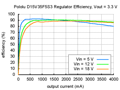
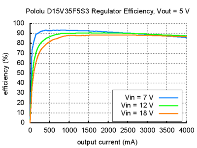
Typical Efficiency
The efficiency of a voltage regulator, defined as (Power out)/(Power in), is an important measure of its performance, especially when battery life or heat are concerns. As shown in the graphs below, this switching regulator typically has an efficiency of 80 to 90%. For example, when regulating 12 V to 5 V with an output current of 1.8 A, the efficiency is 90%. Since the output power is (Output current)×(Vout) = 1.8 A × 5 V = 9 W, the input power will be 10 W, with 1 W of heat dissipated in the regulator. The input current can then be calculated as 10 W/12 V = 0.83 A. This is far better than a linear voltage regulator, which would require an input current of 1.8 A and 22 W, wasting 13 W instead of the 1 W lost in this switching regulator.
Dimensions
- Size: 1.68" x 0.46" x 0.3"
- Weight: 3 g1
General specifications
- Minimum operating voltage: 4.5 V
- Maximum operating voltage: 24 V
- Maximum output current: 4.5 A2
- Minimum output voltage: 3.3 V
- Maximum output voltage: 5 V
- Continuous output current: 3.5 A3
- Reverse voltage protection?: Y
- Maximum quiescent current: 25 mA
Notes:
1.Without included hardware.
2.Threshold for over-current protection. Output current is also limited by thermal dissipation.
3.Typical. Actual continuous output current limited by thermal dissipation.